
A refrigeration pressure transmitter must withstand the circuit’s actual pressure and temperature extremes, remain compatible with the refrigerant and oil, and provide a stable, usable signal during compressor operation. Selection should begin with the measurement function—not the normal operating pressure alone—then account for shutdown equalization, defrost, high-ambient operation, pressure spikes, vibration, condensation, and electrical integration.
For heat pumps, chillers, condensing units, refrigerated cases, and compressor packages, the best transmitter is usually the one with a process-wetted construction, reference range, overload capability, connection, output, and response behavior that match a documented application envelope. A low-cost unit selected only by nominal pressure range can create false trips, weak diagnostics, drift, or premature leakage.
Define the measurement and control function
First identify what pressure is being measured and what decision depends on it. Refrigeration pressure measurements are commonly used for:
- Compressor suction-pressure control or low-pressure protection
- Discharge-pressure monitoring and high-pressure shutdown
- Condensing-pressure or head-pressure control
- Electronic expansion valve control
- Defrost and heat-pump mode-change logic
- Refrigerant charge, leak, or performance diagnostics
- Compressor load, oil-management, and system fault analysis
- Differential-pressure monitoring across filters, evaporators, or oil circuits
A pressure transmitter converts process pressure into a continuous electrical signal. The controller, variable-speed drive, building automation system, or protective relay interprets that signal. Unlike a mechanical pressure switch, a transmitter allows trending, diagnostics, setpoint changes, and control loops, but it also introduces considerations such as signal scaling, supply voltage, grounding, and response time.
Specify the pressure reference correctly
Pressure can be expressed as gauge pressure or absolute pressure.
- Gauge pressure is measured relative to local atmospheric pressure. It is commonly shown as psig.
- Absolute pressure is measured relative to a vacuum. It is commonly shown as psia.
This distinction is especially important on low-side circuits and during evacuation or leak testing. A transmitter referenced to atmosphere will not provide the same numeric reading as an absolute-reference transmitter at the same physical condition.
The relationship is approximately:
P absolute = P gauge + P atmospheric
For an illustrative sea-level example:
P absolute = 30 psig + 14.7 psi = 44.7 psia
Atmospheric pressure changes with elevation and weather, so 14.7 psi is an example rather than a universal conversion value. Define the controller’s expected reference before selecting the instrument and scaling its output.
Separate control measurement from safety protection
A transmitter used for normal control is not automatically the sole protective device for every hazard. Determine whether the measurement supports:
- A routine control loop
- A warning alarm
- A shutdown command
- A permissive for compressor starting
- Independent safety protection
- A diagnostic input only
The required fault response, independence, wiring method, and verification approach can differ substantially. The equipment designer should identify applicable product, electrical, refrigerant, and site safety requirements for the installation rather than assuming that a pressure transmitter alone fulfills all protective functions.
Map normal pressure, transients, and fault conditions
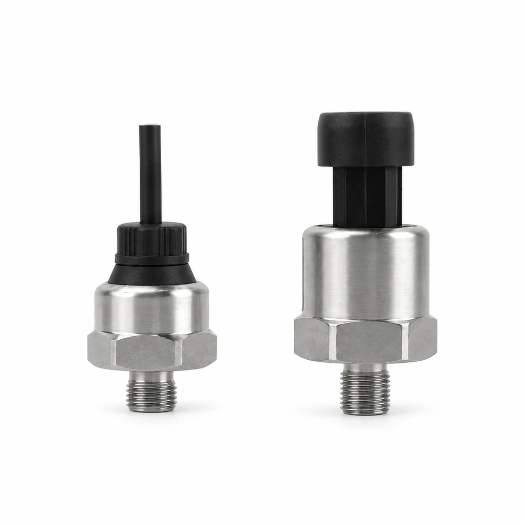
Normal suction and discharge readings do not define the full transmitter duty. Refrigeration pressure transmitter selection should be based on the complete pressure envelope over the equipment lifecycle.
Create a pressure profile for each measurement point that includes:
- Expected minimum operating pressure
- Expected maximum operating pressure
- Startup and shutdown conditions
- Pump-down and equalization behavior
- Defrost and reversing-valve transitions
- High ambient or reduced heat-rejection conditions
- Fan, valve, or control failure scenarios
- Service operations, charging, recovery, and pressure testing
- Transport, storage, and non-operating temperature conditions
Account for dynamic pressure events
Compressor systems can produce rapid pressure changes that are not visible in slowly sampled supervisory trends. Sources include:
- Compressor discharge pulsation
- Reciprocating compressor pressure ripple
- Fast valve closure or solenoid switching
- Hot-gas defrost
- Reversing-valve actuation in heat pumps
- Liquid slugging or abnormal flow conditions
- Rapid compressor cycling
- Pressure-test exposure during manufacture or service
Pulsation is a repeated pressure variation around the average pressure. It can create noisy readings, accelerate mechanical fatigue, and cause unstable control if the transmitter, mounting arrangement, or controller filtering is unsuitable.
Do not solve every pulsation issue by applying excessive software filtering. Heavy filtering can delay high-pressure alarms and degrade expansion-valve or fan-control performance. Instead, identify whether the issue is process pulsation, an unsupported impulse line, electrical noise, inappropriate transmitter response, or poor control-loop tuning.
Size for the maximum credible pressure, not the typical reading
The selected measurement range must cover the maximum pressure that can occur at the transmitter port, including applicable operational and service states. The transmitter’s specified overload and burst limits must also be reviewed separately.
These terms are different:
| Term | Meaning | Selection implication |
|---|---|---|
| Measuring range | Pressure interval represented by the output signal | Must cover the intended control and diagnostic range |
| Overpressure or overload rating | Pressure the transmitter may withstand without specified damage, subject to manufacturer conditions | Must cover credible transient exposure |
| Burst pressure | Pressure at which mechanical failure may occur under stated test conditions | Not a usable operating allowance |
| Proof pressure | A defined pressure exposure used to verify integrity or performance in some specifications | Confirm the exact manufacturer definition |
Do not treat burst pressure as an acceptable pressure-test target or as a substitute for range and overload selection.
Confirm refrigerant, oil, and seal compatibility
The wetted materials—the surfaces exposed to refrigerant, lubricant, and contaminants—must be suitable for the specific circuit. Compatibility cannot be confirmed from the word “refrigeration” alone because refrigerants, lubricants, additives, cleaning agents, and moisture exposure vary by system.
Document the following before finalizing a transmitter:
- Refrigerant designation and blend, verified against the official ISO 817 search record or the applicable project standard
- Lubricant type, such as mineral oil, alkylbenzene, polyolester, or polyvinyl ether
- Expected lubricant carryover at the measurement point
- Presence of cleaning chemicals, dyes, or sealants
- Maximum and minimum fluid temperatures
- Expected moisture exposure and service procedures
- Wetted metal, elastomer, adhesive, and fill-fluid compatibility requirements
Why oil and seal selection matter
A transmitter diaphragm may be metallic while its internal seals, joining materials, and other wetted components are not. Refrigerant-oil mixtures can behave differently than either fluid alone, especially across repeated temperature cycles. A compatible metal port does not by itself prove compatibility of the complete wetted assembly.
Confirm compatibility using the transmitter manufacturer’s documented wetted-material information and the refrigerant, oil, and equipment-material guidance applicable to the system. When an application uses a new refrigerant-lubricant combination, do not infer suitability from a similar legacy fluid.
Avoid cross-contamination assumptions
Service practices can introduce unexpected materials. Thread compounds, sealants, flushing agents, and charging-hose residues may contact the sensing port. Specify installation materials that are appropriate for the system and avoid allowing excess compounds to migrate into the pressure passage.
If the transmitter is installed where oil pooling, debris accumulation, or liquid refrigerant trapping is likely, assess the port orientation and fitting geometry. The aim is not necessarily to eliminate oil exposure—many refrigeration locations experience it—but to avoid creating a blocked, delayed, or mechanically stressed pressure path.
Evaluate temperature cycling, condensation, and vibration
A transmitter is exposed to two different temperatures:
- Media temperature: the temperature of refrigerant and oil at the process connection
- Ambient temperature: the air temperature around the transmitter housing, connector, cable, and electronics
Both must remain within the manufacturer’s stated limits. A transmitter mounted on a hot discharge line may see high media temperature while its electronics are affected by radiant heat. A suction-line instrument can experience low surface temperature, condensation, and frost even in an otherwise moderate equipment enclosure.
Consider thermal cycling and thermal error
Temperature changes can affect zero point, span, mechanical stress, and output electronics. The published accuracy of a transmitter may apply at defined reference conditions; installed performance can be less accurate when media and ambient temperatures cycle widely.
Total installed measurement uncertainty is not the same as transmitter accuracy alone. A practical conceptual model is:
Total uncertainty = sensor error + temperature effect + mounting effect + electrical signal error + controller scaling error
This is not a direct arithmetic formula for every specification method. Some errors are systematic, some vary over time, and some may combine statistically. It is useful because it prevents an unrealistically narrow view of accuracy.
For example, a precise transmitter can still produce poor control if a long, vibrating pressure line creates a delayed pressure signal, the analog input is scaled incorrectly, or electrical interference adds noise.
Manage condensation and ingress paths
Condensation is common near evaporators, suction piping, outdoor heat-pump equipment, and cold equipment rooms. Water can enter through a damaged connector seal, an improperly terminated cable, or a cable path that directs water toward the electrical connection.
Good installation practices include:
- Position connectors and cable entries to reduce water collection.
- Use the specified mating connector, cable, and sealing components.
- Provide strain relief so cable movement does not load the connector.
- Avoid damaged threads, seals, and connector gaskets.
- Route cables to form a drip loop where appropriate.
- Keep electrical enclosures and unused entries properly sealed.
Confirm the transmitter’s environmental protection characteristics for the completed assembly, not only for the bare sensor body. A housing may have a stated protection level only when paired with the correct connector and installation method.
Treat vibration as a mounting-system issue
Compressors, fans, pipework, and transport can impose vibration. A transmitter installed directly on a vibrating line may be exposed to both mechanical vibration and pressure pulsation.
To reduce risk:
- Use a mechanically supported connection rather than allowing the transmitter to act as a pipe support.
- Avoid rigid cable routing that transfers vibration into the connector.
- Follow the recommended tightening method and torque from the fitting or transmitter documentation.
- Assess whether a remote mounting arrangement is appropriate where vibration is severe.
- Verify that any impulse tubing or capillary connection will not introduce blockage, leakage, or unacceptable response delay.
Choose pressure reference, range, and overload margin
Choose a range that preserves useful resolution in the operating region while accommodating the full credible pressure envelope. An excessively broad range can make small pressure changes difficult to resolve after output scaling and analog-to-digital conversion. An excessively narrow range can expose the transmitter to overload or clip its output during legitimate operating events.
Use a documented range-selection method
For each measurement point, record:
- Minimum expected pressure
- Normal control band
- Maximum expected operating pressure
- Maximum credible transient pressure
- Maximum service or test pressure at the installed location
- Required measurement resolution
- Required alarm and shutdown thresholds
- Required reference: gauge or absolute
An illustrative calculation shows why output scaling matters. Suppose a 4–20 mA transmitter is configured for 0–500 psig.
Pressure per mA = 500 psig / 16 mA = 31.25 psig per mA
A 5 psig process change corresponds to:
Signal change = 5 psig / 31.25 psig per mA = 0.16 mA
Whether that is adequate depends on transmitter uncertainty, analog-input resolution, electrical noise, and control requirements. The calculation does not establish a universal acceptable range; it simply shows why range should be selected deliberately.
Do not confuse pressure with saturation temperature
Technicians often interpret refrigerant pressure through a pressure-temperature relationship. That relationship depends on the refrigerant and, for blends, may depend on whether bubble point or dew point is relevant. A pressure transmitter measures pressure, not saturation temperature or superheat directly.
To calculate superheat or subcooling, the system also needs a valid temperature measurement, the correct refrigerant property relationship, and appropriate measurement locations. Pressure transmitter selection should therefore be coordinated with the temperature-sensor strategy when the control system relies on saturation calculations.
Match process connection, electrical output, and response
The process fitting must match the equipment port, pressure rating, sealing method, installation space, and service practice. Confirm thread form and sealing approach rather than assuming that similar-looking connections are interchangeable.
Threaded connections may seal at the thread, at a gasket, at an O-ring, or at a metal-to-metal seat depending on the fitting design. Applying thread sealant where the design relies on another sealing method can cause leakage, contamination, or misleading installation torque.
Select the output for the control architecture
Common transmitter outputs include analog current, analog voltage, and digital interfaces. Select the output based on the receiving device and the installed electrical environment.
| Output type | Typical advantage | Key check |
|---|---|---|
| 4–20 mA current loop | More tolerant of voltage drop over longer cable runs than voltage signals | Confirm loop supply, input type, load limits, and grounding approach |
| Voltage output | Straightforward for compatible short-run control inputs | Confirm supply regulation, cable length, noise exposure, and input impedance |
| Digital output | Can provide structured data and diagnostics where supported | Confirm protocol, addressing, wiring topology, controller compatibility, and failure behavior |
A transmitter and controller can be electrically connected yet still be incompatible. Confirm:
- Supply voltage range
- Output type and scaling
- Two-wire, three-wire, or four-wire wiring arrangement
- Input resistance or load requirements
- Connector pinout
- Fault indication behavior
- Sampling interval and controller input filtering
- Shielding and grounding practices
- Common reference requirements for voltage signals
Match response to the application
Response time is the delay between a pressure change and the corresponding output response under defined conditions. It matters more for rapidly changing compressor control, electronic expansion-valve control, and protective functions than for slow supervisory monitoring.
However, the installed response may be dominated by the process connection. A restricted port, trapped oil, long impulse tube, or remote manifold can delay the pressure seen by the sensing diaphragm. Evaluate the full measurement path, not just the transmitter datasheet response.
For applications centered on compressor and refrigerant circuits, review the relevant configuration details of a compressor and refrigerant pressure transmitter or a refrigerant pressure transmitter against the documented application envelope. Model suitability must be confirmed from the current product documentation, not assumed from a product category.
Plan installation, commissioning, and diagnostics
Installation errors often look like transmitter failures. Commissioning should verify the mechanical pressure path, electrical signal, controller scaling, and process plausibility as separate checks.
Installation practices that protect measurement quality
Before energizing the system:
- Verify the part number, pressure reference, range, process connection, output, and electrical pinout against the approved submittal.
- Inspect the port and fitting for damage, contamination, and incorrect sealing material.
- Install the transmitter using the specified fitting method; do not apply torque through the electrical connector or housing unless the manufacturer explicitly permits it.
- Support nearby tubing, piping, and cable to prevent mechanical loading.
- Route wiring away from high-noise conductors where practical.
- Confirm the sensor is located at the intended hydraulic or refrigerant pressure point, not across an unintended restriction.
- Check that service access does not require twisting the transmitter body or cable.
Commission output scaling before relying on alarms
For a linear 4–20 mA output, controller conversion is commonly represented as:
Pressure = (Measured current - 4 mA) / 16 mA × calibrated span + lower range value
Illustrative example: a transmitter range is 0–500 psig and the controller measures 12 mA.
Pressure = (12 mA - 4 mA) / 16 mA × 500 psig + 0 psig
Pressure = 250 psig
This example assumes a linear 4–20 mA signal, correct loop measurement, and a 0–500 psig configured range. It does not apply to every output type or to a transmitter with a different lower range value.
Commissioning should compare the indicated value with a suitable reference at defined pressure points where practical. Record the reference instrument, conditions, test points, actual readings, and acceptance criteria established by the project.
For an OEM or project inquiry, specify the required range, output, connection, instrument identification and acceptance criteria. If calibration or inspection records are required, contact our team to confirm their availability and scope for the selected configuration, including test points, reference information and reported results.
Diagnose common field symptoms
| Symptom | Possible causes to investigate |
|---|---|
| Reading fixed at minimum or maximum | Open circuit, wrong supply, incorrect pinout, output scaling error, transmitter fault, blocked port |
| Noisy pressure value | Compressor pulsation, electrical interference, poor grounding, loose connector, inadequate input filtering |
| Reading differs from service gauge | Gauge versus absolute reference mismatch, inaccurate reference gauge, different measurement location, temperature effects, scaling error |
| Slow response | Restricted port, trapped oil, long impulse path, controller filtering, sampling delay |
| Repeated high-pressure alarms | Genuine heat-rejection problem, wrong range scaling, transient spikes, poor sensor location, unstable control loop |
| Intermittent faults in wet conditions | Condensation at connector, damaged cable seal, water path through cable routing, inadequate enclosure sealing |
Do not replace a transmitter before checking the process pressure with an appropriate reference, confirming the controller conversion, and inspecting the electrical and mechanical installation.
Use an OEM application data checklist
A complete application record makes a transmitter selection defensible and reduces rework during prototype testing, procurement, and field commissioning.
Refrigeration pressure transmitter specification checklist
Process and system
- Measurement location: suction, discharge, liquid line, oil circuit, receiver, or differential point
- Refrigerant identification and blend information
- Lubricant type and expected oil carryover
- Gauge or absolute pressure reference
- Minimum, normal, maximum, and transient pressures
- Media temperature range and ambient temperature range
- Startup, shutdown, defrost, reversal, pump-down, and service conditions
- Pressure-test and recovery procedures relevant to the installed location
Performance and control
- Required measuring range and useful control band
- Required overload and mechanical pressure capability
- Accuracy requirements across expected temperature conditions
- Required response behavior and allowable filtering delay
- Alarm, trip, permissive, and diagnostic functions
- Controller scaling, sampling, and fault-response logic
Mechanical and environmental
- Wetted-material and seal compatibility confirmation
- Process connection type, thread form, and sealing method
- Space, orientation, access, and service-tool clearance
- Vibration, pulsation, shock, and pipe-support conditions
- Condensation, washdown, dust, and cable-entry conditions
Electrical and documentation
- Supply voltage and wiring configuration
- Output type, range scaling, and receiving-input compatibility
- Connector, cable, shielding, grounding, and strain-relief requirements
- Identification, traceability, inspection, and documentation needs
- Commissioning reference, test points, and acceptance criteria
For related non-refrigerant high-pressure auxiliary circuits, such as certain equipment hydraulic functions, a hydraulic pressure transmitter should be evaluated independently because fluid compatibility and pressure behavior differ from refrigerant service.
Turn the checklist into a one-page application specification, then compare candidates against their current datasheets and installation instructions. The HPT-12 refrigerant pressure transmitter offers current, voltage and RS485 versions with G1/2 or G1/4 connection options. Confirm the selected version’s pressure and temperature limits and compatibility with the exact refrigerant, lubricant and seals; the product’s refrigeration designation alone does not establish suitability for every circuit.
Technical sources and further reading
- ASHRAE standards and guidelines for refrigeration-system and safety context.
- ISO search for ISO 817 for official refrigerant designation and safety-classification information.
Technical references are linked in the article. Confirm product-specific requirements against the selected configuration.