
A 4-20 mA pressure transmitter circuit works only when the transmitter type, supply arrangement, receiver input, and wiring polarity are compatible. Start with the transmitter terminal diagram and the PLC, indicator, or controller input documentation—not wire colors alone.
For a two-wire transmitter, the same pair of conductors supplies power and carries the measured current. Three-wire and four-wire devices separate power and signal functions, but their output may be active or passive. That distinction determines whether the receiving circuit supplies loop power. The standardized analogue-signal context is documented in IEC 60381-1; terminal assignments still come from the specific device documentation.
Identify the transmitter and input type before wiring
Before landing any conductors, identify both ends of the circuit. “4-20 mA” describes the signal range, not a universal terminal arrangement.
Confirm these items from the transmitter and input documentation:
- Number of transmitter wires: Two, three, or four.
- Supply type and voltage range: Usually DC, but the permitted operating range varies by model.
- Output type: Active current source, passive current output, isolated output, or non-isolated output.
- Input type: Passive current input, active/current-sourcing input, voltage input used with a resistor, or a configurable analog input.
- Input burden or resistance: The voltage dropped by the PLC, recorder, indicator, isolator, and any other series devices.
- Terminal labels: For example,
+,−,SIG,COM,OUT,PWR, orI+andI−. - Grounding requirements: Especially where a device has a functional earth terminal, shield clamp, intrinsic-safety interface, or isolated signal circuit.
- Pressure range and engineering units: Such as 0-100 psi, −15 to 15 psi, 0-10 bar, or 0-250 inH2O.
Do not assume wire color conventions are consistent across products. A red conductor may be supply positive in one cable assembly and signal positive in another. Terminal markings and the product-specific wiring diagram take precedence.
A field connector can also change how terminals are accessed. If a transmitter uses that connector format, verify pin assignments at both the transmitter and cable end; a DIN 43650 field connector should be wired according to the applicable device terminal diagram rather than assumed pin numbering.
Match active and passive devices
An active output supplies the current signal from its own powered electronics. A passive output regulates current but needs external loop power. Similarly, an analog input may be:
- Passive: It measures incoming current and does not provide loop voltage.
- Active: It provides a loop excitation voltage intended for a passive field device.
- Voltage-only: It measures voltage, such as 1-5 VDC, and requires a correctly selected external resistor to convert current to voltage.
Connecting an active transmitter output to an active input can place two power sources in opposition. Connecting a passive transmitter output to a passive input can leave the circuit unpowered. Confirm the source of loop voltage before wiring.
Understand two-wire loop current operation
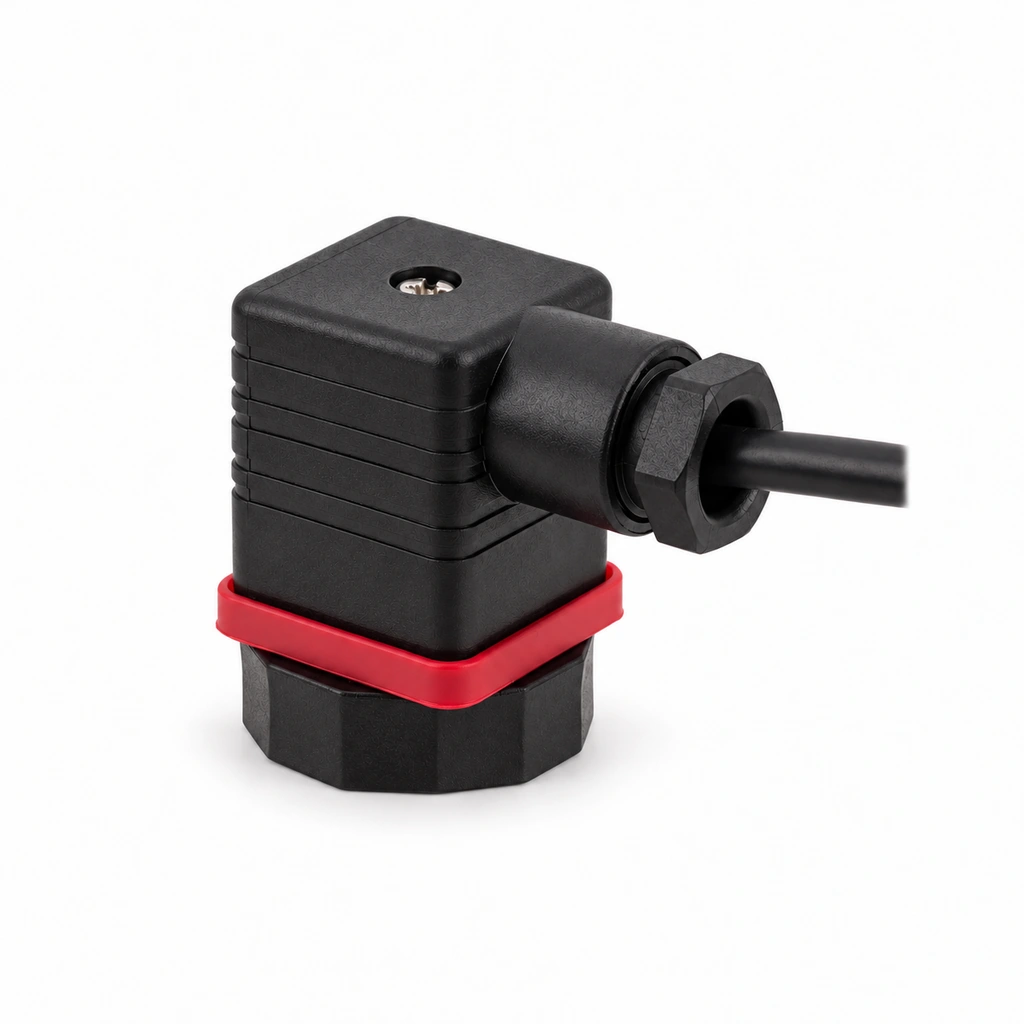
A two-wire 4-20 mA pressure transmitter is commonly called a loop-powered transmitter. It uses one pair of wires for both DC supply power and signal current.
At the lower-range value (LRV), the transmitter normally regulates loop current to 4 mA. At the upper-range value (URV), it normally regulates to 20 mA. Current between those values represents pressure proportionally for a linear configuration.
A typical conceptual two-wire circuit is:
DC supply + → transmitter + → transmitter − → PLC current input + → PLC current input − → DC supply −
The exact terminal order may differ. Some PLC cards use a shared common terminal, while others have isolated channels. Follow the channel-specific diagram.
Why the signal starts at 4 mA
The 4 mA lower limit provides operating current for loop-powered electronics and permits fault discrimination. A reading near 0 mA can indicate an open circuit, loss of supply, incorrect wiring, or a failed component. However, fault-current behavior is configuration-specific. Do not assume every transmitter signals faults at the same current values.
Convert loop current to pressure
For a linear transmitter:
Pressure = LRV + [(Measured current − 4 mA) / 16 mA] × (URV − LRV)
Where:
- Pressure is the calculated process pressure.
- LRV is the pressure assigned to 4 mA.
- URV is the pressure assigned to 20 mA.
- Measured current is the loop current in mA.
Example only: Assume a transmitter is ranged from 0 to 100 psi and the measured loop current is 12 mA.
Pressure = 0 psi + [(12 mA − 4 mA) / 16 mA] × (100 psi − 0 psi)
Pressure = 50 psi
This calculation is valid only when the transmitter output is configured as linear over that stated range. It does not confirm that the process pressure itself is accurate; installation effects, calibration condition, impulse lines, temperature, and the reference instrument can all contribute to total measurement uncertainty.
Wire three-wire and four-wire outputs correctly
Three-wire and four-wire transmitters are usually externally powered rather than loop-powered. Their wiring is not interchangeable with a two-wire loop.
Three-wire transmitters
A three-wire transmitter typically has:
- Supply positive:
PWR+ - Supply common:
PWR−orCOM - Signal output:
OUTorSIG
A common arrangement is:
DC supply + → PWR+
DC supply − → PWR− / COM
Signal OUT → PLC analog input
PLC input return → PWR− / COM
This arrangement shares the power return and signal reference. It can work well in a properly designed system, but voltage drops in the shared common conductor can become a measurement error when high current loads or long cable runs use the same return path.
Use separate conductors and appropriate commoning practices where the manufacturer specifies them. Do not connect the analog signal return to a protective earth conductor unless the documentation explicitly requires that arrangement.
Three-wire devices may provide either a voltage or current output. A 4-20 mA output should connect to a compatible current input. If the transmitter instead provides 0-10 VDC, 1-5 VDC, or another voltage signal, do not connect it directly to a current-only input.
Four-wire transmitters
A four-wire transmitter generally has separate power terminals and separate signal output terminals:
DC supply + → PWR+
DC supply − → PWR−
Signal OUT+ → PLC input +
Signal OUT− → PLC input −
Because the output pair is separate, it may be galvanically isolated from the power circuit—or it may not be. Isolation must be confirmed in the datasheet; wire count alone does not prove it.
A four-wire transmitter can have:
- An active 4-20 mA output, which drives current into a passive receiving input.
- A passive 4-20 mA output, which requires a separate signal-loop supply in addition to the transmitter’s operating supply.
- A voltage output, sometimes paired with a separate power supply.
For a passive current output, the signal loop may be arranged as:
Loop supply + → transmitter signal output + → transmitter signal output − → PLC input + → PLC input − → loop supply −
Terminal polarity varies by design. Never use a generic diagram as a substitute for the device manual.
Avoid an unintended common reference
When several non-isolated three-wire transmitters share a supply, their signal commons may be electrically connected. This can cause unexpected interactions if channels are connected to isolated inputs, different grounded panels, or equipment with separate power supplies.
Check whether each analog input is:
- Single-ended or differential
- Isolated or non-isolated
- Internally referenced to analog common
- Shared across multiple channels
For systems with mixed grounding schemes, remote equipment, or significant electrical noise, isolated analog inputs or signal isolators may be appropriate—but their voltage burden must be included in the loop calculation.
Calculate loop voltage and load resistance
A two-wire transmitter needs enough voltage across its terminals to operate at the highest required loop current. Every series component consumes part of the available voltage.
Use this basic loop-voltage check:
Supply voltage ≥ Transmitter minimum operating voltage + (Maximum loop current × Total series resistance)
Where:
- Supply voltage is the available DC voltage at the source, in volts.
- Transmitter minimum operating voltage is the minimum voltage required at the transmitter terminals.
- Maximum loop current is usually 20 mA for normal operation, or a higher documented value if the device can signal above-range or diagnostic conditions.
- Total series resistance includes PLC input resistance, indicator resistance, isolator resistance, safety barrier resistance, fuse resistance where material, and both conductors of cable resistance.
Illustrative loop-budget calculation
Assume:
- 24 VDC nominal supply
- Transmitter requires at least 10 VDC at its terminals
- PLC input resistance is 250 ohms
- Cable plus other series resistance is 100 ohms
- Maximum normal signal current is 20 mA, or 0.020 A
The voltage required by the series resistance is:
Voltage drop = 0.020 A × (250 ohms + 100 ohms)
Voltage drop = 7 V
The loop requires:
10 V + 7 V = 17 V
With a nominal 24 VDC supply, the estimated margin is:
24 V − 17 V = 7 V
This example suggests the loop has voltage margin under the stated assumptions. It does not prove the design is adequate. Confirm the lowest possible supply voltage at the panel and transmitter, account for power-supply tolerance, cable temperature, barriers, and any documented over-range current.
Determine the maximum allowable load
Rearrange the voltage equation to estimate maximum total series resistance:
Maximum total resistance = (Minimum available supply voltage − Transmitter minimum operating voltage) / Maximum loop current
Assume the lowest available supply voltage is 20 VDC, the transmitter requires 10 VDC, and the design must support 20 mA:
Maximum total resistance = (20 V − 10 V) / 0.020 A
Maximum total resistance = 500 ohms
That 500 ohms is the total allowable series resistance for the entire loop, not just the PLC input. If the PLC already contributes 250 ohms, only 250 ohms remain for cable and other devices.
Using a 250-ohm resistor for a voltage input
A 250-ohm precision resistor converts 4-20 mA into approximately 1-5 VDC:
Voltage = Current × Resistance
At 4 mA:
0.004 A × 250 ohms = 1 V
At 20 mA:
0.020 A × 250 ohms = 5 V
This can be useful when a control system accepts voltage rather than current. However, resistor tolerance, temperature coefficient, input impedance, grounding arrangement, and loop voltage budget all affect the result. Use a resistor appropriate for the required measurement uncertainty and power dissipation.
Choose cable shielding, grounding, and routing
A current loop is generally less sensitive to induced voltage than a low-level voltage signal, but it is not immune to noise, ground loops, poor terminations, or electromagnetic interference.
For most industrial 4-20 mA pressure transmitter wiring, use a twisted pair sized for the installation environment and voltage-drop calculation. Use shielded twisted pair where the route is electrically noisy, cable runs are long, or the installation specification calls for shielding.
Apply shields deliberately
A cable shield reduces capacitive and electromagnetic coupling when it is terminated correctly. A common approach is to ground the shield at one end only, usually at the control-panel or receiving-equipment end. This reduces the chance that shield current flows due to different ground potentials.
Important exceptions exist:
- Equipment-specific installation instructions may require a different shield termination.
- High-frequency interference control may use specialized 360-degree shield termination methods.
- Hazardous-area interfaces and intrinsically safe systems require the applicable design documentation and approved installation method.
- Shielding is not a substitute for a proper protective-earth system.
Keep the shield insulated and isolated at the non-grounded end unless the design calls for another method. Do not use a signal cable shield as the normal DC power return.
Route signal cable away from noise sources
Avoid running analog signal cable in parallel with:
- Variable-frequency drive output conductors
- Motor feeders
- Contactors and relay coil wiring
- Welding leads
- High-current DC conductors
- Fast-switching power supplies
Where crossing is unavoidable, cross at approximately 90 degrees where practical. Maintain separation according to the project wiring standard and the electrical environment. A shield cannot always correct noise introduced by poor routing.
Check polarity, scaling, and engineering units
Correct electrical continuity is only part of a successful installation. The receiving system must interpret the signal using the same range and units as the transmitter.
Verify polarity before power is applied
For a two-wire loop, reversed polarity may result in no current, a fixed current, or no operation, depending on transmitter protection design. For three-wire and four-wire devices, reversing supply polarity, signal polarity, or both can produce misleading symptoms.
Label each wire at both ends and verify:
- Supply positive and supply negative
- Signal positive and signal negative
- Signal common versus power common
- Shield drain-wire termination
- Channel number and PLC terminal assignment
Configure scaling in the PLC or indicator
Set the analog input scaling to match the transmitter range. For a standard 4-20 mA input:
- 4 mA = LRV
- 20 mA = URV
Example: A 0-300 psi transmitter should normally be scaled as:
- 4 mA = 0 psi
- 20 mA = 300 psi
A transmitter ranged for 0-10 bar should not be displayed as psi unless the controller applies the correct conversion and the displayed units are clearly labeled.
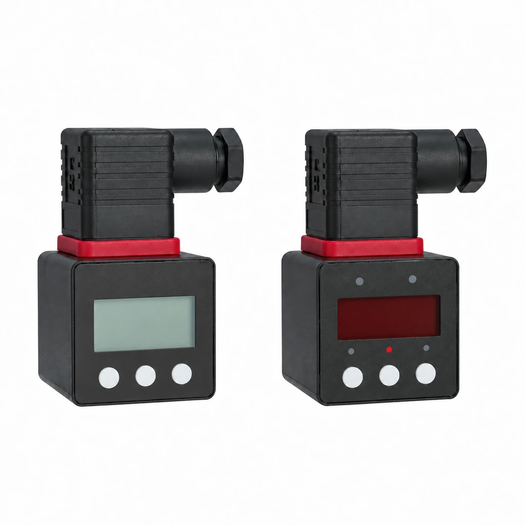
Local displays also need matching range information. When considering a digital display module for pressure or temperature, confirm compatibility with the transmitter’s electrical output, connector arrangement, range configuration, and intended engineering units.
Separate accuracy from installed uncertainty
A transmitter’s stated accuracy describes the instrument under defined reference conditions. The actual installed measurement uncertainty can also include:
- Pressure reference uncertainty during calibration
- PLC analog-input accuracy and resolution
- Resistor tolerance for current-to-voltage conversion
- Cable resistance and supply variation
- Temperature effects
- Zero shift from mounting orientation, depending on the transmitter design
- Process connection issues, pulsation, trapped gas, plugged impulse paths, or leaks
- Incorrect range, units, or scaling
A correctly wired loop can still report an inaccurate process value if these factors are not addressed.
Troubleshoot zero current, fixed current, and noisy signals
Troubleshooting should distinguish a wiring issue from a pressure-measurement issue. Use a calibrated loop meter, process calibrator, or suitable multimeter in the correct mode and input jack. Opening a live loop to insert a meter can interrupt the process signal, so follow the site work procedure.
Zero current or near-zero current
Likely causes include:
- No DC supply voltage
- Open fuse, open conductor, loose terminal, or damaged connector
- Reversed polarity on a device without reverse-polarity protection
- Passive transmitter output connected to a passive input with no loop supply
- Incorrect meter connection or meter fuse failure
- Failed transmitter or receiving input
Check supply voltage at the transmitter terminals while connected, not only at the power supply. A voltage measured with the transmitter disconnected may not reveal a high-resistance connection or an overloaded supply.
Fixed current
A signal fixed near 4 mA may mean the process pressure is genuinely at the lower range. It can also result from a plugged pressure port, incorrect range configuration, failed sensor element, output saturation, or a transmitter diagnostic state.
A signal fixed near 20 mA may indicate actual high pressure, an over-range process condition, incorrect scaling, a blocked reference path on gauge-pressure equipment, or a fault condition defined by that product.
Do not diagnose a transmitter solely from one current value. Compare the loop reading with a known pressure source or an approved signal simulation method, and review the device’s documented fault behavior.
Noisy or unstable signal
Common causes include:
- Electrical interference from nearby power equipment
- Poor shield termination or shield grounded at multiple points
- Ground-potential differences between field and panel equipment
- Loose terminals, moisture ingress, or connector corrosion
- Insufficient supply voltage margin
- Rapid real process pressure changes, pulsation, or pump cycling
- Mechanical vibration or an unsuitable process connection
- PLC filtering set too low or too high for the process
First determine whether the current measured at the transmitter is unstable. If the transmitter current is stable but the PLC value fluctuates, investigate the input channel, scaling, common reference, wiring path, or control-system configuration. If the loop current itself changes, determine whether the cause is process variation, transmitter behavior, or power integrity.
For hydraulic systems, pressure pulsation and mechanical vibration deserve particular attention. A hydraulic pressure transmitter should be selected and installed with the actual pressure range, connection, media compatibility, electrical interface, and expected dynamic conditions verified for the equipment.
Use a pre-energization and commissioning checklist
Use this checklist for a datasheet review, panel inspection, or field commissioning pack.
Before energizing
- Confirm transmitter wire count: two-wire, three-wire, or four-wire.
- Confirm whether the transmitter output is active or passive.
- Confirm whether the PLC or receiver input is active, passive, current, or voltage type.
- Verify the terminal diagram for the exact transmitter configuration.
- Verify supply voltage at the field device, including the lowest expected operating voltage.
- Calculate total loop resistance and confirm adequate voltage margin at maximum required current.
- Confirm cable conductor size, route, shield type, and shield termination plan.
- Check polarity, terminal torque, conductor identification, and connector assembly.
- Confirm pressure connection, media compatibility, pressure range, and engineering units.
- Verify PLC channel configuration and 4-20 mA scaling.
During commissioning
- Measure loop current at a known or simulated low-end condition.
- Measure loop current at a known or simulated high-end condition where safe and practical.
- Confirm the displayed engineering value agrees with the expected current-to-pressure conversion.
- Verify the current at the transmitter and the value at the controller agree.
- Check for signal noise with nearby equipment operating under normal conditions.
- Record as-left configuration: range, units, supply voltage, loop current, input channel, and wiring revision.
- Restore covers, strain relief, shielding, grounding, and environmental seals after testing.
For a general industrial pressure application, the HPT-6 diffused silicon pressure transmitter provides a starting point for comparing 4–20 mA and other output configurations. Confirm the selected version’s wire count, terminal assignment, supply limits and permitted loop load against its wiring documentation; the availability of a 4–20 mA option does not establish the connection details for every version.
FAQ
Can a 4-20 mA transmitter share a power supply with other instruments?
Yes, many systems use a shared DC power supply. The supply must have adequate capacity, each loop must have a valid return path, and the grounding/common-reference design must avoid unwanted current paths. Isolated channels or dedicated loop supplies may be preferable where ground-potential differences are likely.
Can I test a 4-20 mA loop with a standard multimeter?
Yes, if the meter is rated and configured for DC current measurement and is connected correctly in series with the loop. Be aware that inserting a meter opens the circuit unless test terminals or a loop test point are provided. A loop calibrator or clamp-style milliamp meter designed for low-current signals can reduce disruption.
Does longer cable always require a larger power supply?
Not always, but longer cable increases loop resistance and voltage drop. Calculate the voltage available at the transmitter at maximum loop current. If the margin is insufficient, reduce resistance, use a suitable higher supply voltage within device limits, or revise the loop architecture.
A defensible 4-20 mA pressure transmitter installation starts with the exact terminal diagrams, a complete voltage budget, compatible active/passive devices, and documented scaling. Include those checks in the equipment specification and commissioning record before placing the loop into service.
Technical sources and further reading
- IEC 60381-1 for analogue direct-current signals used in process control systems.
- IEC 61326-1 catalogue for EMC requirements applicable to electrical measurement and control equipment.
Technical references are linked in the article. Confirm product-specific requirements against the selected configuration.