
There is no universal pressure transmitter calibration frequency. A transmitter in a stable, noncritical utility service may justify a longer interval than one protecting product quality, controlling a critical process, or supporting a safety-related decision. Start with the manufacturer’s guidance, then set and revise the interval using process risk, service conditions, calibration history, and as-found performance, consistent with the evidence-based approach in OIML D 10.
For a new installation with no history, many teams begin with a conservative baseline interval—often one year—then use documented as-found results to either maintain, shorten, or carefully extend it. That starting point is a planning assumption, not a technical requirement. The correct interval is the longest period that still provides acceptable confidence in the installed measurement.
Choosing an initial calibration interval
Set the calibration interval according to the consequence of an undetected error and the evidence that the transmitter remains stable in service.
| Measurement situation | Initial interval approach | Reason to reassess sooner |
|---|---|---|
| Safety-related trip, protective shutdown, or high-consequence process control | Use a conservative interval defined by the site’s risk and functional requirements | Any as-found error near the acceptance limit, process upset, impulse-line issue, or abnormal mechanical event |
| Custody, quality, or tightly controlled batch measurement | Use a documented interval based on required uncertainty and product-quality risk | Shift in yield, balance discrepancy, suspected overpressure, or repeatability concern |
| General closed-loop process control | Start with manufacturer guidance and a conservative site baseline | Control-loop oscillation, offset between related measurements, frequent temperature cycling |
| Stable indication or noncritical utility monitoring | Consider a longer interval only after favorable as-found history is established | Exposure to vibration, plugging, corrosion, freezing, or maintenance disturbance |
| New duty, new transmitter model, or changed installation | Use a short learning interval | No historical drift evidence exists for the new configuration |
A calendar interval alone is incomplete. A pressure transmitter can drift because of sensor aging, diaphragm stress, electronics aging, thermal cycling, vibration, pressure pulsation, corrosion, plugged impulse paths, or a zero shift after installation work. Some of those effects are gradual; others occur suddenly after an event. A risk-based program therefore combines periodic calibration with event-driven checks.
A pressure transmitter generally converts pressure-induced diaphragm deflection into an electrical measurement, then conditions that signal into an output such as current, voltage, or a digital value. Calibration confirms the relationship between applied pressure and reported output over the required range. It does not prove that every installed pressure connection, impulse line, manifold, seal, or control-system scaling issue is correct.
Separate calibration, verification, and adjustment
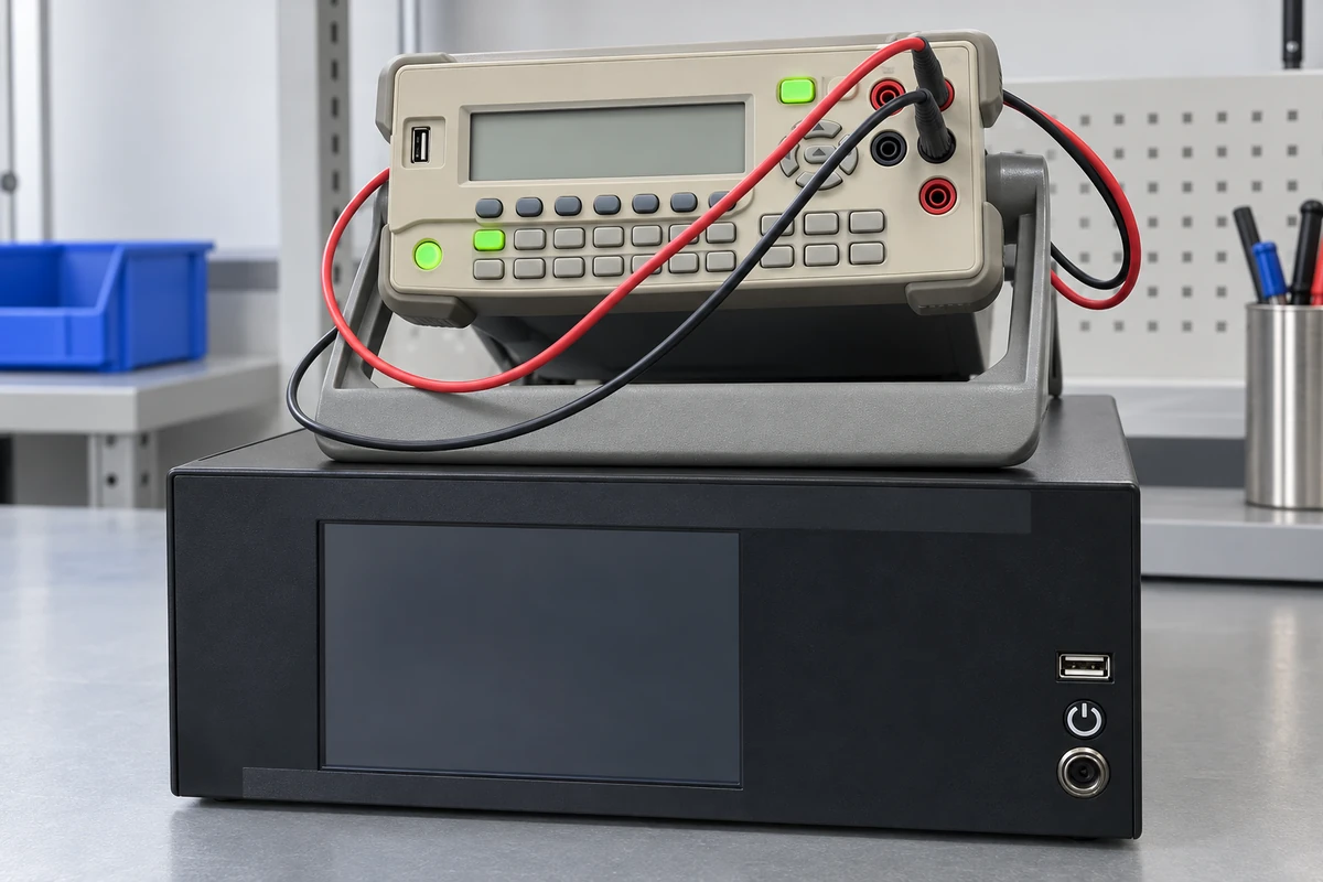
These terms are often used interchangeably, but they support different decisions.
Calibration is a comparison of the transmitter indication or output with a suitable reference at defined input points. The result establishes measurement error at the time of the test. A calibration can be performed without changing the transmitter.
Verification is a check that a device or measurement loop meets a defined acceptance criterion. It may be a limited check, such as confirming zero and span points, or it may include a full multi-point comparison. A verification should state exactly what was tested.
Adjustment changes the transmitter’s configuration or trim so its output more closely agrees with the reference. Adjustment should follow a documented decision rule. Adjusting every device automatically can erase useful drift evidence and can introduce configuration risk.
As-found data are the results recorded before adjustment, repair, or replacement. This is the most valuable information for setting pressure transmitter calibration frequency. As-left data are recorded after any adjustment or corrective action and demonstrate the condition returned to service.
A loop check is separate again. It tests the signal path from transmitter through wiring, barriers or isolators where applicable, control-system input, engineering-unit scaling, alarms, and display. A perfectly calibrated transmitter can still produce a wrong control-room value if the loop is scaled incorrectly.
Rank each measurement by process risk
The interval should reflect the impact of bad data, not merely the transmitter purchase price. Rank every measurement before assigning a frequency.
Consider these questions:
- What happens if the measurement is wrong but remains plausible? Identify consequences for personnel, equipment, emissions, product quality, energy use, and production continuity.
- Does the transmitter initiate an alarm, trip, permissive, or automated control action? An error in a protective or shutdown function usually warrants stronger controls than a local indicator.
- What pressure range is actually used? A transmitter operating close to zero pressure or at a narrow portion of a broad calibrated range may have less useful process resolution.
- Can another measurement reveal an error? Redundant instruments, material balance checks, and independent gauges can reduce detection time but do not eliminate the need for calibration.
- How quickly can error develop? Rapid plugging, corrosion, vibration damage, or thermal shock changes the risk profile.
- What is the allowed process error? Work backward from the process decision—not from a generic transmitter accuracy statement.
A simple risk ranking can use three categories:
- High risk: Incorrect pressure could defeat a protective decision, damage equipment, cause major quality loss, or remain undetected for a long period.
- Moderate risk: Incorrect pressure degrades control, throughput, maintenance planning, or routine product consistency, but independent controls limit the consequence.
- Lower risk: The reading is advisory, is easily cross-checked, and an error has limited operational consequence.
Do not label a measurement “low risk” simply because it is not safety-related. A noncritical pressure reading on a filter, pump, or pneumatic system can still drive unnecessary maintenance or conceal an expensive developing fault.
Use manufacturer guidance and site history correctly
Manufacturer guidance is the right starting point because it may address the transmitter design, range, sensing technology, and intended service limits. However, it cannot fully determine the interval for an installed process. The calibration interval also depends on site-specific pressure cycling, ambient temperature variation, vibration, contaminants and required measurement uncertainty.
Use manufacturer information to confirm:
- Recommended calibration or verification practices
- Supported calibration range and allowable configuration
- Required stabilization time, test medium, and mounting considerations
- Output behavior during test and adjustment
- Effects of static pressure, temperature, position, or process connection on the measurement
- Restrictions on applying pressure, venting, or using device trim functions
Then use site history to determine whether the initial interval is appropriate. Historical results are useful only when the comparison is meaningful. Grouping all “pressure transmitters” together can hide important differences. Separate data by factors such as:
- Transmitter family and calibrated range
- Service medium and wetted-material exposure
- Process temperature and ambient environment
- Installation type, including direct mount, remote seal, or impulse-line system
- Pressure cycling and vibration exposure
- Criticality class
- Whether the device was adjusted, repaired, moved, or exposed to an abnormal event
A transmitter that repeatedly passes in clean, stable nitrogen service does not establish an interval for a similar-looking instrument on a vibrating pump discharge or a corrosive process line.
For new equipment, procurement documents should ask for the information needed to build the program: calibrated range, output configuration, accuracy basis, environmental limitations, process connection, materials, and recommended verification method. Configurable instruments, including general-purpose pressure transmitter options, should be evaluated against the actual installation and calibration requirements rather than selected by pressure range alone.
Account for environment, cycling, and mechanical stress
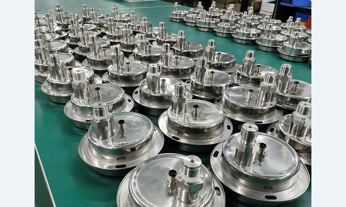
Pressure transmitter drift is not caused only by elapsed time. Duty cycle and installation conditions can dominate performance.
Temperature and thermal cycling
Changes in ambient or process temperature can affect the sensing element, electronics, fill fluid where used, wiring, and mounting hardware. A unit operating at a steady temperature may be stable for years, while the same unit exposed to repeated hot-cold cycles may show a changing zero or span.
Evaluate:
- Seasonal ambient swings in outdoor installations
- Heat conducted through process connections
- Steam-out, washdown, startup, and shutdown cycles
- Enclosure heating from nearby equipment
- Condensation and freeze-thaw exposure
A calibration performed in a controlled shop may not reproduce the installed thermal condition. Where temperature effects are important, document the test conditions and consider an installed verification at representative operating conditions.
Pressure cycling, pulsation, and overpressure events
Repeated pressure reversals, fast pulsation, water hammer, compressor surge, and pump starts impose mechanical stress. The transmitter may still provide a signal but can develop zero shifts or reduced repeatability.
Review whether the application needs pulsation damping, a snubber, a different mounting arrangement, or a transmitter range better suited to normal operating pressure. These are engineering decisions that must account for process response time; excessive damping can conceal a rapid pressure change that the control or protection function must detect.
Any suspected overpressure, process excursion, dropped instrument, or substantial piping modification should trigger an event-driven calibration check. Waiting for the next scheduled interval may be inappropriate.
Vibration, moisture, corrosion, and plugged pressure paths
Vibration can loosen fittings, damage wiring, or introduce intermittent output problems. Moisture ingress and corrosion may affect terminals, connectors, and enclosures. In differential-pressure applications, plugged impulse lines, unequal fill levels, leaking manifolds, or valve lineup errors can create large installed errors that bench calibration will not identify.
For differential-pressure service, the appropriate device must be considered together with the primary element, impulse system, and mounting arrangement. A differential-pressure transmitter for applicable hazardous-area installations still requires confirmation that the complete installation, not just the instrument, suits the process and site requirements.
Set acceptance limits and reference uncertainty
An acceptance limit is the maximum permitted error before corrective action is required. It should be based on the measurement’s role in the process, including the uncertainty contributed by the transmitter, calibrator, installation, and control system.
Do not confuse transmitter accuracy with total installed measurement uncertainty. Transmitter accuracy describes the device under stated reference conditions and a stated basis. The process decision sees the combined effects of multiple contributors.
A simplified uncertainty estimate can be expressed as:
U_combined = sqrt(U_transmitter² + U_reference² + U_test_method² + U_installation²)
Where:
U_combined= estimated combined uncertainty, in pressure units or percent of calibrated spanU_transmitter= uncertainty associated with the transmitterU_reference= uncertainty of the pressure reference at the test pointU_test_method= effects of fittings, resolution, repeatability, operator technique, and stabilizationU_installation= effects such as head pressure, temperature, impulse-line condition, or mounting
This equation is a simplified root-sum-square estimate and assumes the contributors are independent. If errors are correlated or a known bias exists, use a method that represents that condition instead of applying the formula mechanically.
Illustrative uncertainty calculation
Assume a transmitter is calibrated over 0 to 100 psi. At a test point, the estimated contributors are:
- Transmitter uncertainty: 0.30 psi
- Reference uncertainty: 0.10 psi
- Test-method uncertainty: 0.10 psi
- Installation uncertainty: 0.20 psi
U_combined = sqrt(0.30² + 0.10² + 0.10² + 0.20²) psi
U_combined = sqrt(0.15) psi = 0.39 psi
This illustrative result means the estimated combined uncertainty is approximately 0.39 psi, or 0.39% of the 100 psi span. It does not establish that 0.39 psi is acceptable. The process owner must compare it with the allowed measurement error for the control, alarm, quality, or maintenance decision.
The reference must be suitably accurate and controlled for the required acceptance limit. If the reference uncertainty consumes most of the permissible error, the comparison cannot confidently distinguish an in-tolerance transmitter from an out-of-tolerance one. Define the required confidence before choosing the calibrator.
Also specify the error basis. Common choices include percent of calibrated span, percent of reading, or pressure units. A limit of ±1% of span has very different practical meaning at 5 psi than at 95 psi on a 0–100 psi calibration range.
Use as-found data to extend or shorten intervals
As-found data turn calibration from a recurring task into a measurement-control program. At each completed calibration, record the actual deviation at each point before any adjustment. Then trend results across comparable instruments and service conditions.
An interval may be cautiously extended when all of the following are true:
- The transmitter has multiple consecutive, documented as-found results comfortably within its acceptance limit.
- No result shows a worsening drift trend.
- The process, range, installation, and operating environment have not materially changed.
- Event-driven checks have not revealed damage or instability.
- The reference and test method are sufficiently capable to support the decision.
Shorten the interval when a device fails as-found, approaches the limit, shows increasing drift, suffers repeated installation problems, or operates in a newly severe environment. Investigate the cause before simply increasing calibration frequency. A six-month interval does not solve a plugged impulse line, poorly supported piping, pressure pulsation, incorrect range selection, or recurrent overpressure.
A useful drift-rate screen is:
Drift rate = absolute as-found error / time since previous acceptable calibration
For example, assume a transmitter is found 0.60 psi from reference after 18 months. Its illustrative average drift rate is:
0.60 psi / 18 months = 0.033 psi per month
If the acceptance limit is 1.00 psi and the site reserves margin for uncertainty and unexpected change, this calculation may support a revised interval. But it is only a trend indicator. Drift is rarely perfectly linear, and one result cannot establish a reliable long-term rate.
Never extend an interval only because the instrument was adjusted to pass. The decision must be based on its as-found condition.
Create a documented calibration program
A defensible program makes the decision criteria visible, repeatable, and reviewable. It should define what is calibrated, how it is tested, what constitutes acceptance, and how history changes future intervals.
Include the following in each instrument record:
- Unique instrument tag, location, service, process risk category, and criticality
- Manufacturer, model, serial number where available, calibrated range, units, and output configuration
- Required engineering range and alarm or control relevance
- Acceptance limits, including the error basis
- Calibration procedure, test points, direction of travel, stabilization requirements, and required loop checks
- Reference equipment identification and its current calibration status
- Environmental or installation observations, such as vibration, leaking connections, plugged lines, corrosion, or damaged wiring
- As-found results, adjustment performed, repair details, and as-left results
- Due date, assigned interval, reason for the interval, and criteria for review after a failure or process change
A practical workflow is:
- Classify the measurement by process consequence and detection capability.
- Define the required process uncertainty and acceptance limit.
- Select a capable reference and written test method.
- Set a conservative initial interval using manufacturer guidance and comparable site experience.
- Record as-found and as-left results separately.
- Investigate failures and near-failures for underlying installation or process causes.
- Review trends at defined intervals and change frequencies only with documented justification.
For equipment manufacturers and integrators, include calibration access and maintainability in the design phase. Leave adequate space for test connections, specify isolation and venting arrangements where needed, identify required test ranges, and ensure that the transmitter range supports both process control and meaningful verification.
Pressure transmitter calibration checklist
Use this checklist when preparing a datasheet, request for quotation, commissioning package, or field calibration work order:
- Identify the process consequence of a wrong pressure value.
- Define normal, minimum, maximum, and transient process pressures.
- Select a calibrated range that provides useful resolution without exposing the sensor to expected excursions.
- Confirm process connection, wetted materials, temperature exposure, vibration, and environmental conditions.
- Define whether the task is calibration, verification, adjustment, loop check, or all four.
- Set acceptance limits in psi, percent of span, or percent of reading, with the basis stated.
- Confirm reference uncertainty is appropriate for the acceptance decision.
- Specify test points, increasing/decreasing pressure checks where needed, and stabilization time.
- Record as-found results before adjustment.
- Set the next pressure transmitter calibration frequency using risk, duty, and trend evidence.
- Require an event-driven check after overpressure, severe vibration, process changes, or relevant maintenance.
For a new or replacement instrument in a general industrial pressure application, review the HPT-6 diffused silicon pressure transmitter against the required range, connection, output and service conditions. Ask for the selected version’s stability information, calibration procedure and available records before setting an interval. Hazardous-area installations require separate verification of the exact instrument’s approvals and installation conditions.
Technical sources and further reading
- OIML D 10 — Guidelines for the determination of calibration intervals for risk- and history-based interval review.
- JCGM measurement uncertainty publications for uncertainty terminology and evaluation principles.
- NIST Technical Note 1297 for expressing measurement uncertainty.
Technical references are linked in the article. Confirm product-specific requirements against the selected configuration.