HPT-L / HPT-F
Flow and Heat Totalizer
HPT-L flow and heat calculation instrument with configurable flow, pressure-compensation and temperature-compensation inputs. HPT-F is the reference used for the square panel configuration.
- Accuracy
- ±0.2% FS
- Serial-interface options
- Two-wire RS485 or three-wire RS232; Modbus RTU
- Communication rate
- 1200–19200 bps
Supplied by WKSENSOR. Ask us about pricing, availability and delivery.
Product overview
The HPT-L is a flow and heat calculation instrument. Its input configuration can combine a flow signal with pressure and temperature compensation, or provide an uncompensated flow-totalizing configuration.
The HPT-F square panel configuration provides flow and heat totalization for steam applications.
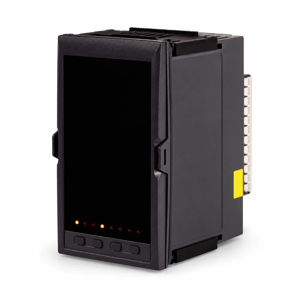
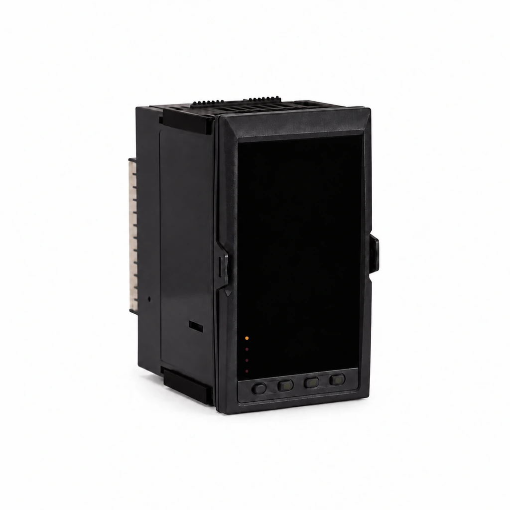
Vertical panel configuration
Tall black enclosure with a glass front, a lower row of status points and keys, side mounting features and a terminal strip at the rear.
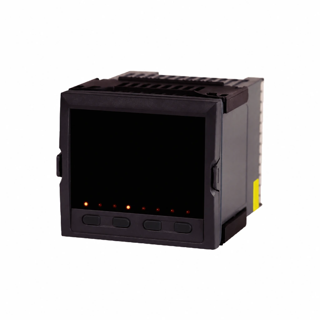
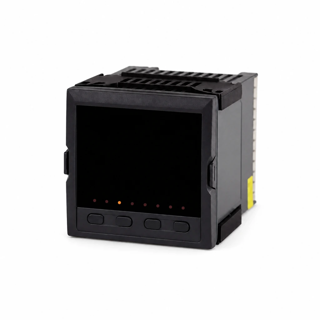
HPT-F square panel configuration
A square glass front sits above a lower row of keys. The rear enclosure has ventilation slots, side mounting clips and a yellow side label.
Flow and compensation connections
The first input accepts the configured flow voltage, current or pulse signal. The second input provides pressure compensation or outlet temperature; the third provides temperature compensation or inlet temperature. An uncompensated flow-totalizing configuration omits the compensation inputs.
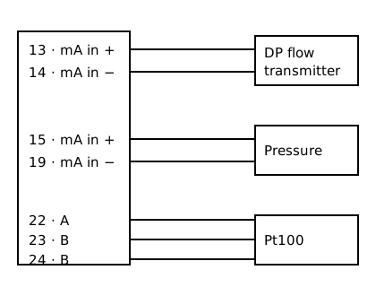
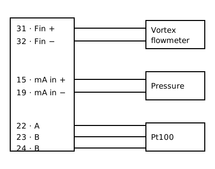
The following differential-pressure and vortex examples use pressure and three-wire Pt100 temperature compensation. Terminal arrangements differ between case formats.
Differential-pressure flow input
Flow: 13 (+) / 14 (−). Pressure compensation: 15 (+) / 19 (−). Three-wire Pt100: 22 (A) / 23 (B) / 24 (B).
Vortex pulse input
Flow pulse: 31 (Fin+) / 32 (Fin−). Pressure and Pt100 compensation use the same terminal references as the differential-pressure example.
| Terminals | Reference |
|---|---|
| 7 / 8 | 24 V DC excitation + / − |
| 9 / 10 | Second 24 V DC excitation + / − |
| 11 / 12 | L / N in the illustrated mains-powered circuit |
External-signal input codes
Flow configurations use voltage, current or pulse input. Pressure-compensation configurations use voltage or current input. Temperature configurations use the corresponding temperature-input type. The ranges below describe the configured external signal.
| Code / type | Input range |
|---|---|
| 00 · B | 400–1800 °C |
| 01 · S | 0–1600 °C |
| 02 · K | 0–1300 °C |
| 03 · E | 0–1000 °C |
| 04 · T | −200.0–400.0 °C |
| 05 · J | 0–1200 °C |
| 06 · R | 0–1600 °C |
| 07 · N | 0–1300 °C |
| 08 · F2 | 700–2000 °C |
| 09 · Wre3–25 | 0–2300 °C |
| 10 · Wre5–26 | 0–2300 °C |
| 11 · Cu50 | −50.0–150.0 °C |
| 12 · Cu53 | −50.0–150.0 °C |
| 13 · Cu100 | −50.0–150.0 °C |
| 14 · Pt100 | −200.0–650.0 °C |
| 15 · BA1 | −200.0–600.0 °C |
| 16 · BA2 | −200.0–600.0 °C |
| Code / signal | Input range / type |
|---|---|
| 17 · Linear resistance | 0–400 Ω |
| 18 · Remote resistance | 0–350 Ω |
| 19 · Remote resistance | 30–350 Ω |
| 20 · Millivolt | 0–20 mV |
| 21 · Millivolt | 0–40 mV |
| 22 · Millivolt | 0–100 mV |
| 23 · Millivolt | −20–20 mV |
| 24 · Millivolt | −100–100 mV |
| 25 · Current | 0–20 mA |
| 26 · Current | 0–10 mA |
| 27 · Current | 4–20 mA |
| 28 · Voltage | 0–5 V |
| 29 · Voltage | 1–5 V |
| 30 · Voltage | −5–5 V |
| 31 · Voltage | 0–10 V · fixed input type |
| 32 · Current, square-root conversion | 0–10 mA |
| 33 · Current, square-root conversion | 4–20 mA |
| 34 · Voltage, square-root conversion | 0–5 V |
| 35 · Voltage, square-root conversion | 1–5 V |
| 36 · Pulse | 0–10 kHz |
The millivolt, current, voltage and resistance rows list a −1999–9999 numerical scale. Additional selections are 55: configurable input type, 56: special specification, and X: no input.
Configuration and selection
Analogue-output load references
| Signal version | Load resistance |
|---|---|
| 4–20 mA / 0–20 mA | ≤500 Ω |
| 0–10 mA | ≤1 kΩ |
| 1–5 V / 0–5 V | ≥250 kΩ |
| 0–10 V | ≥4 kΩ |
- Analogue retransmission
- OUT1 and OUT2 are independently selected. Codes: X — no output; 0 — 4–20 mA; 1 — 1–5 V; 2 — 0–10 mA; 3 — 0–5 V; 4 — 0–20 mA; 5 — 0–10 V; 8 — special specification.
- Alarm outputs
- Codes: X — no relay alarm; 1 — one alarm output; 2 — two alarm outputs.
- Communication and printing
- D1 — RS485 Modbus RTU; D2 — RS232 Modbus RTU; D3 — RS232 printing interface; Y — external start/stop/reset input. Printing configurations support manual, timed or alarm-triggered printing.
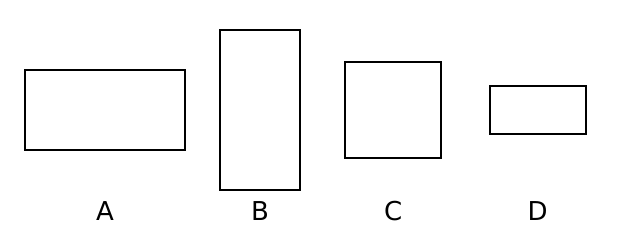
Case formats by reference code
| Code / format | Dimensions |
|---|---|
| A · Horizontal | 160 × 80 × 110 |
| B · Vertical | 80 × 160 × 110 |
| C · Square | 96 × 96 × 110 |
| D · Horizontal | 96 × 48 × 110 |
Serial communication
| RS485 reference | Two-wire · ≤1000 m |
|---|---|
| RS232 reference | Three-wire · ≤15 m |
| Framing | 1 start bit · 8 data bits · 1 stop bit · no parity |
| Protocol / rate | Modbus RTU · 1200–19200 bps |
Transmitter-feed selections
- X
- No feed output
- 1P
- One feed output
- 2P
- Two feed outputs
Configuration examples: 2P(24) denotes two 24 V feed outputs; 2P(12) denotes two 12 V feed outputs. The 24 V reference configuration is rated 24 ±1 V DC, ≤30 mA with load resistance ≥750 Ω.
| Contact reference | Rating |
|---|---|
| Small contact | 125 V AC / 0.5 A or 24 V DC / 0.5 A |
| Large contact | 220 V AC / 2 A or 24 V DC / 2 A |
Technical reference
Specifications and options
| Parameter | Specification or option |
|---|---|
| Model | HPT-L / HPT-F |
| Instrument function | Flow and heat calculation / totalization |
| Display | LED numerical indication |
| Accuracy | ±0.2% FS |
| Input selection | 37 selectable signal types in the input family |
| Alarm function | Upper/lower limits with adjustable alarm deadband |
| Serial-interface options | Two-wire RS485 or three-wire RS232; Modbus RTU |
| Communication rate | 1200–19200 bps |
| Transmitter excitation output | DC 24 V ±1 V; ≤30 mA with load resistance ≥750 Ω |
| Power-supply alternatives | AC/DC 100–240 V, 50/60 Hz; or DC 12–36 V |
| Power consumption | ≤5 W for the 100–240 V version; ≤3 W for the DC 12–36 V version |
| Operating environment | −10–50 °C; non-condensing and non-icing |
| Brand | WKSENSOR |
| Product reference | HH-844021220147 |
Application scenarios
Flow and heat calculation applications include industrial control, industrial automation, petrochemical processes, metallurgy, power, water treatment and heat treatment. The HPT-F configuration also lists steam metering and paper production.

Oil
Pump equipment and oil-field pipework.

Chemicals
Columns, process vessels and steel pipework.
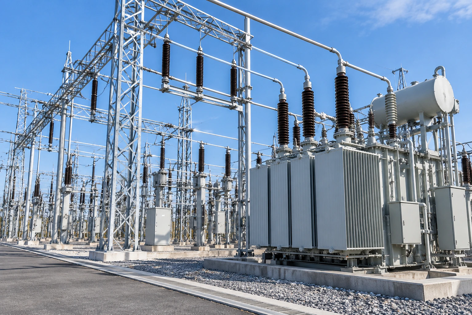
Power
Outdoor power equipment and supporting structures.

Energy
Solar panels across a renewable energy site.

Water
Treatment tanks and surrounding metal walkways.