
A pressure sensor, pressure transducer, and pressure transmitter may all measure pressure, but they are not interchangeable names in a specification. In the most useful engineering distinction, a sensor is the sensing element, a transducer converts pressure into an electrical signal, and a transmitter provides a conditioned output designed to communicate with a control or monitoring system.
The terminology is not used consistently across all catalogs. JCGM measurement terminology provides the metrology context, but a purchasing specification should still select the device by its pressure reference, wetted materials, output signal, power requirement, accuracy, environmental limits, and installation requirements—not by the product name alone.
Which pressure device do you need?
Use a pressure sensor when your electronics will read a low-level or raw sensing signal and handle excitation, scaling, filtering, and diagnostics.
Use a pressure transducer when you need a pressure measurement converted to an electrical output, often voltage, current, frequency, or a digital value. In practice, “transducer” commonly refers to compact pressure devices with an amplified output.
Use a pressure transmitter when the pressure signal must travel reliably to a PLC, DCS, remote I/O module, data logger, or building automation controller. A transmitter commonly provides a standardized output such as 4–20 mA, 0–10 V, or an industrial digital communication interface.
Use a pressure switch when the required outcome is an on/off action at a defined pressure threshold. Use a pressure gauge when a local person needs to read pressure at the process connection.
The right choice depends on the measurement architecture:
| Need | Usually the best fit | Why |
|---|---|---|
| Embedded OEM electronics | Sensor or low-level-output transducer | Allows custom signal conditioning and firmware control |
| PLC analog input several hundred feet away | 4–20 mA transmitter | Current signaling is relatively resistant to voltage drop and electrical noise |
| Short cable to a voltage-input controller | Voltage-output transducer or transmitter | Can be simple if power, grounding, and cable length are controlled |
| Direct pump shutdown at a limit | Pressure switch | Provides a discrete control action rather than a continuous measurement |
| Technician verification at the skid | Pressure gauge, often alongside an electronic device | Gives a direct local indication |
| Networked equipment with distributed diagnostics | Digital transmitter | May simplify digital integration if controller and protocol are compatible |
Define sensor, transducer, and transmitter
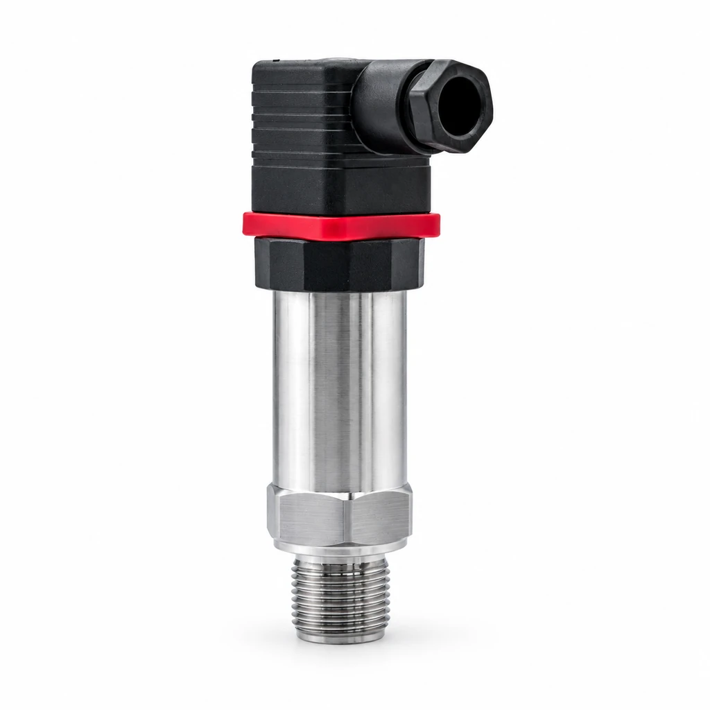
Pressure sensor: the pressure-responsive element
A pressure sensor is the part that physically responds to pressure. Common sensing principles include strain-gauge, piezoresistive, thin-film, capacitive, and ceramic technologies. Pressure changes cause a measurable change in resistance, capacitance, charge, or another electrical property.
A bare or minimally conditioned sensor may produce a low-level output such as millivolts per volt (mV/V). It often needs a stable excitation supply, a precision analog front end, temperature compensation, analog-to-digital conversion, and software scaling.
For example, an illustrative bridge sensor with a sensitivity of 2 mV/V excited at 5.0 VDC produces approximately 10 mV at full-scale pressure:
full-scale output = sensitivity × excitation voltage
10 mV = 2 mV/V × 5.0 V
That is a very small signal. Cable resistance, electromagnetic interference, ground offsets, connector contamination, and amplifier offset can materially affect the final reading. The calculation describes the sensor output only; it does not establish system accuracy.
Pressure transducer: pressure converted into an electrical output
A transducer converts one form of energy or physical quantity into another. In pressure measurement, it converts pressure into an electrical signal. Technically, a sensing element is itself part of that conversion chain, which is why sensor and transducer are often used interchangeably.
In purchasing language, however, a pressure transducer commonly means a packaged device containing:
- A pressure port and wetted diaphragm
- A sensing element
- Basic temperature compensation
- Signal conditioning or amplification
- An electrical connector or cable
- An output such as 0.5–4.5 V, 0–5 V, 0–10 V, 1–5 V, or 4–20 mA
The label does not guarantee output type or signal conditioning. A “pressure transducer” could be a raw bridge-output component, a three-wire voltage device, or a two-wire current-loop device. Read the wiring and output sections of the datasheet.
Pressure transmitter: a measurement device built for communication
A pressure transmitter usually includes the same physical sensing chain plus output conditioning intended for an instrumentation system. It converts pressure into a recognized signal format and is typically configured around a defined pressure range and output span.
The word “transmitter” is especially common where the signal is sent to a control room, PLC, remote I/O rack, SCADA system, or other distant receiver. A transmitter may support analog current, analog voltage, digital serial communication, or a combination of local display and communications.
A transmitter is not automatically more accurate than every transducer. Accuracy depends on the individual product design, calibration range, temperature behavior, stability, and installed conditions. “Transmitter” primarily tells you about the intended signal and system role.
Compare output signals and transmission distance
Signal choice affects noise susceptibility, wiring cost, power architecture, fault detection, and controller compatibility. Confirm the receiving input type before selecting the instrument.
| Output type | Typical wiring | Strengths | Main checks and limitations |
|---|---|---|---|
Raw mV/V bridge |
4, 5, or 6 wires | High flexibility for embedded systems | Requires stable excitation, precision measurement, shielding, and close attention to cable effects |
| Voltage, such as 0–5 V or 0–10 V | Usually 3 wires | Straightforward for short, controlled runs | Voltage drop, ground potential differences, and noise can create reading errors |
| Ratiometric voltage, such as 0.5–4.5 V | Usually 3 wires | Useful when the controller uses the same supply as its analog reference | Supply variation changes output unless measurement is truly ratiometric |
| 4–20 mA | Usually 2 wires for loop-powered devices; sometimes 3 or 4 wires | Good for longer cable runs; live zero helps identify some faults | Verify loop supply voltage, total loop resistance, input type, and intrinsic safety requirements where applicable |
| Digital serial, such as RS-485 | Usually power plus differential communication pair | Can carry scaled data and device information | Requires protocol compatibility, termination, addressing, cable topology, and network commissioning |
Why 4–20 mA is common for remote measurements
In a current loop, the receiving device measures current rather than relying on a voltage level arriving unchanged at the far end of the cable. Normal conductor resistance causes voltage loss, but the transmitter can maintain the commanded current as long as enough loop voltage remains.
An illustrative loop check is:
required supply voltage = transmitter minimum operating voltage + (loop current × total loop resistance)
Assume a transmitter needs at least 12 VDC at its terminals, the loop reaches 20 mA, and the combined cable plus input resistance is 400 ohms:
required supply voltage = 12 V + (0.020 A × 400 ohms) = 20 V
A 24 VDC supply would provide an apparent 4 V margin under these assumptions. This is not a universal sizing rule: use the specific transmitter’s voltage-versus-load limits, account for barriers, surge protection, indicators, and temperature effects, and assess the actual worst-case supply voltage.
The 4 mA live zero also distinguishes a normal zero-pressure reading from an open circuit that drives the loop toward no current. It does not diagnose every fault. A transmitter can still output a plausible current while its process connection is blocked, its pressure reference is wrong, or its calibration is unsuitable for the application.
Voltage outputs need disciplined grounding
A voltage signal can work well on a compact machine where the transmitter and controller share a clean power supply and a short cable route. Problems grow more likely when signal wiring runs beside variable-frequency drive conductors, solenoid wiring, motors, or long unshielded cable trays.
Before choosing voltage output, verify:
- Input impedance and measurement range of the controller
- Whether the input is single-ended or differential
- Supply and analog-reference relationship for ratiometric devices
- Common-mode voltage limits
- Cable length and routing
- Shield termination method
- Grounding architecture between transmitter and receiver
Separate measurement from switching and indication
A continuous pressure measurement, a discrete pressure trip, and a local reading are different functions. Combining them without defining the purpose leads to naming traps.
Pressure switches provide a state, not a pressure value
A pressure switch changes electrical state when pressure crosses a setpoint. It may have adjustable setpoint, fixed setpoint, rising-pressure actuation, falling-pressure actuation, or configurable hysteresis.
Hysteresis is the intentional difference between the switching point in one direction and the reset point in the other. It prevents rapid cycling around a threshold.
For an illustrative pump-control switch:
- Pump stops as pressure rises to
100 psi - Pump restarts as pressure falls to
80 psi
The pressure differential is:
differential = stop pressure − restart pressure
20 psi = 100 psi − 80 psi
This 20 psi differential may be appropriate in one system and unsuitable in another. Tank volume, pump capacity, demand variation, and allowable pressure fluctuation determine the needed switching behavior.
Do not substitute a pressure switch for a transmitter when operators, trending systems, interlocks, or control algorithms need the actual pressure value. Likewise, do not use a transmitter plus PLC logic as a direct replacement for a safety-related switching function without evaluating the complete required safety function.
Pressure gauges provide local indication
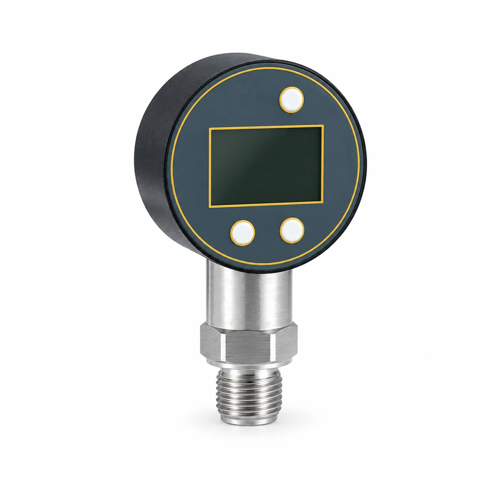
A gauge displays pressure locally, usually through a mechanical movement or an electronic display. It is valuable for setup, troubleshooting, and confirming that a process is pressurized before maintenance.
A gauge does not normally provide a control-system signal. Its reading can also differ from an adjacent transmitter because of gauge accuracy, different process taps, trapped fluid, pulsation, temperature, elevation, or different pressure references.
For critical commissioning points, compare devices only after confirming they share the same pressure source and that isolation valves, snubbers, manifolds, and impulse paths are correctly positioned.
Match each device type to a control system
Start with the control system’s actual interface rather than a preferred device label.
Embedded machinery and OEM designs
An OEM that owns the electronics design may choose a sensor or low-level transducer to control component cost, signal filtering, diagnostics, and calibration strategy. This approach requires responsibility for the full measurement chain.
Specify excitation tolerance, zero and span behavior, temperature compensation, electrical interface, analog filtering, analog-to-digital converter resolution, and production calibration method. A low-level sensor is not a plug-and-play substitute for a transmitter.
For a self-contained machine using a conventional PLC analog input, a voltage or current-output device can reduce electronics design effort. The HPT-6 diffused silicon pressure transmitter is a packaged instrument to compare when a conditioned pressure signal is needed; confirm the exact output, range, media compatibility, and electrical configuration for the application.
PLC and remote I/O systems
For a PLC located away from the process, 4–20 mA remains a practical architecture. It is widely understood by commissioning teams and works with many analog input modules.
Confirm whether the PLC input is:
- Passive and requires a loop-powered transmitter
- Active and supplies loop power
- Configurable for current or voltage
- Isolated or non-isolated
- Capable of detecting under-range or over-range current values
- Connected through an isolator, signal conditioner, or safety barrier
A digital interface should be selected only after checking physical-layer and protocol compatibility. “RS-485” identifies an electrical interface, not the complete communications protocol. Addressing, register mapping, baud rate, parity, termination, and polling behavior must align with the controller. For systems designed around serial communications, evaluate a digital RS-485 pressure transmitter against the project’s network requirements.
Hydraulic power units and mobile equipment
Hydraulic applications commonly involve rapid pressure changes, mechanical vibration, fluid compatibility concerns, and high-pressure transients. Select a device based on maximum working pressure, expected surge pressure, pressure port, wetted materials, response needs, electrical connector retention, and installation location.
A hydraulic pressure transmitter is relevant to this device category, but confirm the complete application envelope rather than assuming any hydraulic-labeled device fits every fluid, pressure spike, or connector arrangement.
Account for accuracy, environment, and installation
The stated accuracy of the instrument is only one contributor to installed measurement uncertainty. A system can use an accurate transmitter and still produce an unreliable process value.
Define the pressure reference before defining the range
Pressure reference errors are among the most consequential specification mistakes.
- Gauge pressure measures relative to local atmospheric pressure.
- Absolute pressure measures relative to a vacuum reference.
- Sealed gauge pressure uses a sealed reference rather than actively venting to atmosphere.
- Differential pressure measures the pressure difference between two process points.
- Compound pressure covers both vacuum and positive gauge pressure.
A vessel operating at 0 psig is approximately at atmospheric pressure, not at zero absolute pressure. A vacuum process specified in absolute units cannot be measured correctly with an ordinary gauge-pressure device unless the atmospheric reference and conversion are deliberately managed.
For outdoor or washdown installations, a vented gauge-pressure transmitter needs a reference path to atmosphere. If the vent is blocked by moisture, dirt, or incorrect cable termination, atmospheric changes can appear as process-pressure error.
Separate instrument accuracy from total installed uncertainty
Instrument specifications can include nonlinearity, hysteresis, repeatability, zero error, span error, temperature effect, and long-term stability. Manufacturers may state these terms differently. Confirm what the stated accuracy includes and whether it applies to the full calibrated span, a particular reference condition, or a specified temperature range.
A simplified uncertainty estimate can be made by root-sum-square when contributors are independent and expressed on a compatible basis:
combined uncertainty = √(u1² + u2² + u3²)
If illustrative contributors are 0.25% of span, 0.20% of span, and 0.15% of span:
combined uncertainty = √(0.25² + 0.20² + 0.15²) = 0.35% of span, approximately
This calculation is only a screening method. It is not valid when errors are correlated, biased in the same direction, or expressed on different bases such as percent of reading versus percent of full scale.
Also assess process-side uncertainty from:
- Plugged pressure ports or impulse lines
- Entrapped gas in liquid measurements
- Condensate in gas measurements
- Hydrostatic head from vertical piping
- Pressure pulsation and water hammer
- Temperature exposure beyond the compensated range
- Sensor elevation relative to the process connection
- Incorrect zeroing after installation
Choose the range for normal operation and abnormal events
The calibrated range should give adequate resolution in the normal operating band while safely accommodating expected pressure excursions within the device’s allowable limits. Do not select a range solely because it matches a nominal line pressure.
Document:
- Normal operating pressure
- Startup and shutdown pressure
- Maximum credible surge or spike
- Vacuum exposure, if any
- Required control or alarm resolution
- Static pressure on each side for differential-pressure measurement
- Consequence of an overrange event
For a nominal 100 psi system, it is not enough to request a “100 psi sensor.” The process may regulate at 100 psi but spike well above that during valve closure, or it may normally operate near 10 psi and require finer resolution than a 0–100 psi span provides.
Installation details can dominate performance
Use fittings, seals, torque practices, and thread forms compatible with the pressure port and process medium. A thread label alone does not ensure mating compatibility. Confirm whether the connection uses a tapered thread, straight thread with seal, face seal, or another geometry.
Add protection only where it solves a defined problem:
- A snubber can reduce pulsation but may slow response.
- A diaphragm seal can isolate aggressive, viscous, sanitary, or high-temperature media but introduces fill-fluid and temperature effects.
- A siphon or cooling element can reduce steam temperature exposure but changes installation response.
- A remote seal or capillary arrangement can make maintenance easier in some layouts but adds its own uncertainty sources.
Use application examples to avoid naming traps
Example: compressed-air receiver monitoring
A facility needs a pressure value at a PLC located in another room and wants trend data plus a low-pressure alarm.
The appropriate starting point is a gauge-pressure transmitter with an output accepted by the PLC, often 4–20 mA for the remote run. A local gauge may be installed at the receiver for maintenance checks. A pressure switch could provide a separate discrete backup function if the control design calls for it, but it does not replace the continuous transmitter signal.
Naming trap: ordering a “pressure sensor” without specifying output may result in a low-level signal unsuitable for the PLC input.
Example: hydraulic test stand
A test stand measures pressure near a pump outlet where pulsation and transient events are expected. The system must record a pressure profile and protect the pump against an excessive-pressure condition.
Use a pressure transmitter or transducer with a range, process connection, dynamic capability, and media compatibility appropriate to the hydraulic circuit. Use the recorded analog or digital value for trending. Handle the overpressure protection function with a properly evaluated control and protection design, which may include a separate switch, relief device, or both.
Naming trap: assuming an electronic transmitter alone protects against every fast transient. The response of the sensor, controller scan time, output logic, and final protective element all matter.
Example: tank level inferred from hydrostatic pressure
A water tank level is inferred from pressure at the tank bottom. The device measures pressure, but the useful process variable is liquid height.
For a static liquid, the relationship is:
pressure = density × gravitational acceleration × liquid height
Where pressure is in pascals, density is in kilograms per cubic meter, gravitational acceleration is approximately 9.81 m/s², and height is in meters.
For water near 1,000 kg/m³ and a level of 2.0 m:
pressure = 1,000 kg/m³ × 9.81 m/s² × 2.0 m = 19,620 Pa
That is approximately 19.6 kPa, before considering temperature-driven density change, reference pressure, tank geometry, foam, process motion, and elevation differences. The pressure transmitter is not a direct level sensor; the control system must scale pressure to level using valid process assumptions.
Naming trap: selecting an absolute-pressure transmitter for an open tank when gauge pressure is needed, or forgetting that a vented reference is required.
Pressure device selection checklist
Use this checklist for a datasheet review, request for quotation, design review, or commissioning work pack.
Measurement definition
- Define the measured variable: gauge, absolute, sealed gauge, differential, vacuum, or compound pressure.
- State normal, minimum, maximum, and transient pressure conditions with units.
- Identify the process medium, temperature, contamination risk, and wetted-material compatibility needs.
- Define the required reading or control resolution at normal operating pressure.
Device and signal architecture
- Decide whether the application needs a sensor, transducer, transmitter, switch, gauge, or a combination.
- Match output type to the actual controller input:
mV/V, voltage, 4–20 mA, or digital communications. - Verify supply voltage, loop resistance, input impedance, isolation, grounding, and cable routing.
- For digital devices, confirm the complete protocol and commissioning parameters—not only the physical interface.
- Specify the process connection, electrical connector, cable requirements, and mounting constraints.
Accuracy and environmental review
- Review accuracy terms, thermal effects, stability, and calibration conditions on the specific datasheet.
- Distinguish device accuracy from total installed measurement uncertainty.
- Check vibration, pulsation, ambient temperature, ingress exposure, and electromagnetic environment.
- Evaluate overpressure, burst, and vacuum exposure requirements against credible process conditions.
- Identify whether snubbers, seals, impulse lines, cooling elements, or isolation valves are needed.
Commissioning checks
- Inspect the correct part number, pressure range, pressure reference, output, and wiring before installation.
- Verify the process connection and sealing method before pressurizing.
- Confirm the controller is scaled to the transmitter range and engineering units.
- Compare the installed reading with a suitable reference at defined points when the procedure requires it.
- Record as-found values, configuration, wiring, and any zero adjustment made in the field.
To compare the different measurement roles, review the HPC-100 digital pressure switch for local indication with relay outputs, or the PM-2000 digital pressure gauge for a display-only battery-powered configuration. These serve different purposes from a continuous-output transmitter. Include the required configuration, acceptance criteria and any calibration documentation in the inquiry, and confirm what can be supplied for the selected instrument.
Technical sources and further reading
- JCGM measurement terminology and publications for internationally recognized measurement concepts and vocabulary.
- IEC 61298 series catalogue for performance evaluation of process measurement and control devices.
Technical references are linked in the article. Confirm product-specific requirements against the selected configuration.